Data Centre Cooling Calculator: Estimate IT Load, PUE & Costs
Data centres are among the most energy-intensive buildings on the planet. A single rack of high-performance servers can draw 30 kW or more, and the cooling system that keeps those servers alive can consume just as much energy as the IT equipment itself. Yet cooling is not optional — without it, servers overheat, throttle, and fail. The challenge for every data centre operator is to deliver enough cooling to protect the IT load, while keeping the overhead — the non-IT energy — as low as possible.
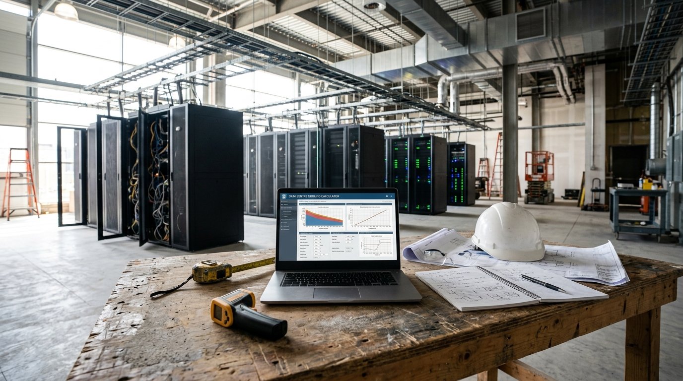
Our Data Centre Cooling Calculator is a free online tool that takes the guesswork out of data centre cooling design. It estimates IT load from racks, floor area, or direct input, applies an effective PUE that reflects the chosen cooling method, calculates cooling capacity with redundancy, estimates free-cooling savings, and provides annual energy consumption and running cost. It supports air-cooled CRAC/CRAH, in-row, rear-door heat exchangers, direct-to-chip liquid cooling, and immersion cooling. Whether you are a data centre designer, facilities manager, or IT manager, this calculator gives you the numbers you need to plan cooling capacity and energy use.
In this guide, we will show you how to use the calculator, explain each input and output, walk through real-world examples, and answer the questions we hear most often. We will also share practical tips to ensure your data centre cooling design is efficient, resilient, and cost-effective.
Data Centre Cooling
Construction CalculatorData centre cooling: IT load, PUE, cooling capacity, redundancy and cost.
What is the Data Centre Cooling Calculator?
The Data Centre Cooling Calculator is a free online tool that estimates the cooling load and energy consumption of a data centre. It supports three IT load input modes (from racks, from floor area, or direct IT load), user-defined PUE target, redundancy level, cooling method, supply and return temperatures, free-cooling strategy, and local pricing. The calculator returns:
- IT load
- Effective PUE
- Facility load
- Cooling load
- Required cooling with redundancy
- Return–supply ΔT
- Air flow (for CRAC/CRAH)
- Free cooling energy saved
- Annual cooling energy
- Other loads per year
- Total facility energy
- Energy per kW IT
- Annual electricity cost
- Cooling capex
The tool is part of a suite of materials and quantities calculators available on our website. For related calculations, you can use our Chiller Sizing Calculator, Cooling Tower Sizing Calculator, Cold Room Cooling Load Calculator, and Air Conditioner Sizing Calculator.
Why Accurate Data Centre Cooling Estimation Matters
Data centre cooling is not just about keeping servers running. It is about resilience, efficiency, and cost control at a scale where small percentage differences translate into enormous energy and financial numbers.
Resilience and Uptime
A data centre that loses cooling can lose its entire IT load within minutes. Every kW of cooling capacity must be available when needed, including during equipment failure. Accurate estimation of cooling load and redundancy ensures the facility can survive a chiller outage, a pump failure, or a hot day without interrupting service.
Energy Efficiency
Data centres consume 1–3% of global electricity, and cooling accounts for 30–50% of that. PUE (Power Usage Effectiveness) is the industry standard for measuring efficiency. A PUE of 1.4 means 40% of the total facility power is overhead; a PUE of 1.2 means only 20%. Accurate estimation of PUE and cooling load helps operators target the low PUEs that reduce cost and carbon footprint.
Capital Cost
Cooling infrastructure is capital-intensive. A 500 kW cooling plant can cost hundreds of thousands of dollars, and redundancy multiplies that figure. Oversizing wastes capital on capacity that may never be used; undersizing risks downtime. Accurate estimation ensures the right capacity at the right cost.
Scalability
Data centres grow in phases. The cooling system must be sized to match current IT load while allowing for future expansion. Accurate estimation of load and capacity supports phased investment and avoids stranded assets.
Compliance and Sustainability
Many jurisdictions regulate data centre energy use, and many operators report PUE publicly. Accurate estimation supports compliance with energy codes, sustainability targets, and reporting requirements.
Liquid Cooling Transition
Modern high-density racks (30–100 kW) cannot be cooled economically with air alone. Liquid cooling — direct-to-chip and immersion — is increasingly common. Each cooling method has a different overhead profile. Accurate estimation helps operators choose the right method for their density and climate.
For more information on data centre cooling principles, you can refer to Wikipedia’s article on data centers or The Green Grid’s PUE guidance.
How to Use the Data Centre Cooling Calculator
Using the calculator is straightforward. Here is a breakdown of each field.
1. IT Load
- Load input: Choose how to estimate IT load:
- From racks: Use this when you know the number of racks and the average power per rack.
- From floor area: Use this for early-stage estimates based on white space area and IT density.
- Direct IT load: Use this when you already know the total IT load from a detailed design.
- Number of racks: Enter the total number of racks. Used in “From racks” mode.
- kW per rack: Enter the average power per rack in kW. Traditional 3–5 kW, modern 10–20 kW, HPC 30–100 kW.
- White space area: Enter the white space area in m² or ft². Used in “From floor area” mode.
- IT density: Enter the IT density in W/m². Typical 300–1500 W/m². Used in “From floor area” mode.
- Total IT load: Enter the total IT load in kW. Used in “Direct IT load” mode.
2. Efficiency
- PUE target: Enter the target PUE for the facility. Excellent 1.2, typical 1.4–1.6, poor > 2.0. The effective PUE is calculated from this value and the cooling method.
3. Redundancy
- Redundancy: Select the redundancy level: N (no redundancy), N+1, 2N, or 2N+1. Higher redundancy multiplies the installed cooling capacity. N+1 adds 20%, 2N doubles it, and 2N+1 adds 120%.
4. Cooling Method
- Cooling method: Select the primary cooling method: CRAC/CRAH (air), in-row/close-coupled, rear-door heat exchanger, direct-to-chip liquid, or immersion. The method determines the effective PUE. Air cooling has the highest overhead; immersion the lowest.
5. Temperatures
- Supply air/water temp: Enter the supply temperature delivered to the servers in °C or °F. Typical 18–24 °C for air, warmer for liquid.
- Return air/water temp: Enter the return temperature from the servers in °C or °F. Typical 30–40 °C for air. The difference is the design ΔT, which determines air or water flow.
6. Free Cooling
- Free cooling: Select none, partial (air-side economizer), or full (water-side economizer). Free cooling reduces mechanical cooling hours.
- Free cooling hours per year: Enter the hours per year when external conditions allow free cooling. Depends on climate. Typical 1000–4000 hours.
7. Pricing
- Capex per kW cooling: Enter the local installed cooling capex per kW.
- Electricity price: Enter the local price per kWh.
- Running hours per year: Enter the expected annual running hours. Data centres typically run 24/7 = 8760 hours.
Once you enter all values, the calculator instantly displays IT load, effective PUE, facility load, cooling load, required cooling with redundancy, return–supply ΔT, air flow, free cooling energy saved, annual cooling energy, other loads per year, total facility energy, energy per kW IT, annual electricity cost, and cooling capex.
Understanding the Calculations
To make the most of the calculator, it is important to understand each output and the underlying formulas.
IT Load
- From racks: rack count × kW per rack.
- From floor area: (area × IT density) / 1000.
- Direct IT load: the value you entered.
Effective PUE
The cooling method reduces the non-IT overhead (PUE − 1) by the cooling factor. The formula is: effective PUE = 1 + (PUE − 1) / cooling factor. By definition, PUE can never be below 1.0, because the IT load is always a subset of the facility load. Cooling factors range from 1.00 (CRAC/CRAH) to 1.70 (immersion).
Facility Load
IT load × effective PUE.
Cooling Load
IT load × (effective PUE − 1) × 0.65. The 0.65 factor represents the share of the non-IT overhead attributable to cooling. The remainder is losses (UPS, PDU, lighting).
Required Cooling with Redundancy
Cooling load × redundancy multiplier. N = 1.0, N+1 = 1.2, 2N = 2.0, 2N+1 = 2.2.
Return–Supply ΔT and Air Flow
ΔT = return temperature − supply temperature, with a minimum of 3 K. Air flow is cooling load / (specific heat of air × ΔT). The result is expressed in m³/h assuming air density of 1.2 kg/m³.
Free Cooling Saving
The calculator models mechanical cooling at COP 3 and free cooling at COP 8. The saving is (mechanical kWh/h − free kWh/h) × free cooling hours × free cooling factor. Partial free cooling uses 50% of the available hours; full free cooling uses 85%.
Annual Cooling Energy
(Compressor annual energy at COP 3) − (free cooling energy saved). Clamped to zero if negative.
Other Loads
Facility load − IT load − cooling load. Represents UPS, PDU, lighting, and other overheads.
Total Facility Energy
Cooling energy + other loads.
Annual Electricity Cost
Total facility energy × electricity price.
Cooling Capex
Required cooling capacity × capex per kW.
Understanding these components helps you interpret the results and adjust your design. For more information on data centre energy, you can refer to The Green Grid or the ASHRAE Handbook.
Example Calculations
Let’s run through two examples to see how the calculator works in different scenarios.
Example 1: Air-Cooled Data Centre, 20 Racks at 5 kW
Inputs:
- Load input: From racks
- Number of racks: 20
- kW per rack: 5 kW
- PUE target: 1.4
- Redundancy: N+1
- Cooling method: CRAC / CRAH
- Supply temp: 20 °C
- Return temp: 32 °C
- Free cooling: Partial
- Free cooling hours: 2000 h
- Capex per kW: $800
- Electricity: $0.15/kWh
- Running hours: 8760 h
Calculations:
- IT load = 20 × 5 = 100 kW
- Cooling factor (CRAC) = 1.00
- Effective PUE = 1 + (1.4 − 1) / 1.00 = 1.40
- Redundancy multiplier (N+1) = 1.20
- Facility load = 100 × 1.40 = 140 kW
- Cooling load = 100 × (1.40 − 1) × 0.65 = 26 kW
- Required cooling = 26 × 1.20 = 31.2 kW
- ΔT air = 32 − 20 = 12 K
- Air flow = 26 / (1.005 × 12) = 2.156 kg/s = 6,468 m³/h
- Free cooling factor (partial) = 0.5
- Mechanical kWh/h = 26 / 3 = 8.67 kWh/h
- Free kWh/h = 26 / 8 = 3.25 kWh/h
- Saving = (8.67 − 3.25) × 2000 × 0.5 = 5,420 kWh/year
- Compressor annual = (26 / 3) × 8760 = 75,920 kWh
- Net cooling energy = 75,920 − 5,420 = 70,500 kWh
- Other loads = 140 − 100 − 26 = 14 kW × 8760 = 122,640 kWh
- Total facility energy = 70,500 + 122,640 = 193,140 kWh
- Annual electricity cost = 193,140 × $0.15 = $28,971
- Energy per kW IT = 193,140 / 100 = 1,931 kWh/kW
- Cooling capex = 31.2 × $800 = $24,960
Result: The air-cooled data centre needs 31.2 kW of installed cooling. Annual facility energy is approximately 193 MWh, with an annual cost of about $28,970.
Example 2: Liquid-Cooled HPC Data Centre, 10 Racks at 30 kW
Inputs:
- Load input: From racks
- Number of racks: 10
- kW per rack: 30 kW
- PUE target: 1.4
- Redundancy: 2N
- Cooling method: Direct-to-chip liquid
- Supply temp: 30 °C
- Return temp: 45 °C
- Free cooling: Full
- Free cooling hours: 3000 h
- Capex per kW: $1,500
- Electricity: $0.12/kWh
- Running hours: 8760 h
Calculations:
- IT load = 10 × 30 = 300 kW
- Cooling factor (liquid) = 1.55
- Effective PUE = 1 + (1.4 − 1) / 1.55 = 1 + 0.258 = 1.258
- Redundancy multiplier (2N) = 2.00
- Facility load = 300 × 1.258 = 377.4 kW
- Cooling load = 300 × (1.258 − 1) × 0.65 = 50.4 kW
- Required cooling = 50.4 × 2.00 = 100.8 kW
- ΔT = 45 − 30 = 15 K
- Air flow = 50.4 / (1.005 × 15) = 3.343 kg/s = 10,030 m³/h
- Free cooling factor (full) = 0.85
- Mechanical kWh/h = 50.4 / 3 = 16.8 kWh/h
- Free kWh/h = 50.4 / 8 = 6.3 kWh/h
- Saving = (16.8 − 6.3) × 3000 × 0.85 = 26,775 kWh/year
- Compressor annual = (50.4 / 3) × 8760 = 147,168 kWh
- Net cooling energy = 147,168 − 26,775 = 120,393 kWh
- Other loads = 377.4 − 300 − 50.4 = 27 kW × 8760 = 236,520 kWh
- Total facility energy = 120,393 + 236,520 = 356,913 kWh
- Annual electricity cost = 356,913 × $0.12 = $42,830
- Energy per kW IT = 356,913 / 300 = 1,190 kWh/kW
- Cooling capex = 100.8 × $1,500 = $151,200
Result: The liquid-cooled data centre needs 100.8 kW of installed cooling with 2N redundancy. Effective PUE is 1.258. Annual energy is approximately 357 MWh, with an annual cost of about $42,830.
These examples show how rack density, cooling method, and redundancy affect the required cooling capacity and annual running cost.
Benefits of Using the Data Centre Cooling Calculator
Tips for Accurate Data Centre Cooling Estimation
- Use the correct IT load. Rack density varies widely. Use real data from server specifications or from a detailed design.
- Set a realistic PUE target. Excellent 1.2, typical 1.4–1.6, poor > 2.0. The cooling method determines how much of the PUE overhead is cooling.
- Choose the right cooling method. Air cooling is suitable for lower densities. Liquid cooling is required for high-density and HPC racks.
- Plan redundancy carefully. N+1 is typical for most facilities. 2N and 2N+1 are used for mission-critical sites.
- Use the correct supply and return temperatures. Higher ΔT reduces flow and pump/fan energy. Modern facilities run warmer supply temperatures to enable free cooling.
- Estimate free cooling hours realistically. Depends on climate. Northern European climates can achieve 4000+ hours; tropical climates may achieve very few.
- Include all facility loads. Cooling is only part of the overhead. UPS, PDU, lighting, and other loads also consume energy.
- Verify with a professional. For mission-critical facilities, have a qualified data centre engineer verify the design.
- Consider phased deployment. Match cooling capacity to IT load growth to avoid stranded assets.
- Monitor and optimise. Use DCIM tools to track PUE and identify inefficiencies over time.
For more information on data centre standards, you can refer to The Green Grid or Wikipedia’s article on data centers.
Common Mistakes to Avoid
- Using air cooling for high-density racks. Above 20 kW/rack, air cooling becomes inefficient and expensive. Liquid cooling is more appropriate.
- Assuming PUE below 1.0 is achievable. PUE is a ratio of facility power to IT power. It can never be below 1.0.
- Forgetting redundancy. Installed cooling capacity must exceed design load to survive equipment failure.
- Underestimating internal gains. Cooling load is a function of IT load and PUE overhead. Do not guess.
- Ignoring free cooling potential. In cool climates, free cooling can save 40–60% of cooling energy.
- Using the wrong ΔT. Lower ΔT increases air or water flow, wasting fan and pump energy.
- Skipping professional verification. For mission-critical facilities, always consult a data centre engineer.
- Over-specifying redundancy. 2N doubles capital cost. Use only where genuinely required.
- Not accounting for other overheads. UPS, PDU, and lighting also consume energy. Include them in the total facility load.
- Ignoring scalability. Data centres grow. Size cooling systems for phased expansion.
How to Reduce Data Centre Cooling Costs
If your estimated energy or cooling cost is higher than expected, here are ways to reduce it without compromising resilience:
- Choose a more efficient cooling method. Liquid cooling reduces PUE significantly compared to air cooling.
- Raise supply temperatures. Warmer supply temperatures allow more free cooling hours and improve chiller efficiency.
- Increase ΔT. Higher ΔT reduces flow and pump/fan energy.
- Implement free cooling. Air-side or water-side economizers reduce mechanical cooling hours.
- Use VFD fans and pumps. Variable-speed control saves energy at part load.
- Improve airflow management. Containment, blanking panels, and hot/cold aisle separation reduce bypass and recirculation.
- Optimise rack density. Higher density within a containment aisle improves cooling efficiency.
- Consider rear-door heat exchangers. RDHx can cool high-density racks without increasing room airflow.
- Use direct-to-chip liquid cooling. For high-density racks, direct-to-chip reduces cooling energy significantly.
- Monitor and optimise continuously. DCIM tools identify inefficiencies and track PUE over time.
- Schedule maintenance. Clean coils, replace filters, and check refrigerant charge regularly.
- Get multiple quotes. Compare cooling suppliers for the best price and performance.
Frequently Asked Questions (FAQ)
Conclusion
The Data Centre Cooling Calculator is an essential tool for data centre designers, facilities managers, and IT managers. It helps you estimate IT load, effective PUE, cooling load, required cooling with redundancy, free cooling savings, annual energy, and running cost. The calculator includes the critical correction that PUE can never fall below 1.0, no matter how efficient the cooling method. By following the tips in this article and using the calculator, you can confidently plan your data centre cooling design and avoid costly sizing mistakes.
Whether you are cooling a small edge facility or a large hyperscale data centre, accurate estimation is the foundation of resilience, efficiency, and long-term cost control. Try the Data Centre Cooling Calculator today and take the guesswork out of your data centre cooling design.