
Cable Size (Three-Phase) Calculator: Choose the Right Conductor Size
Three-phase power is the backbone of industrial, commercial, and large residential electrical systems. From motors and HVAC equipment to distribution boards, three-phase circuits carry higher power with greater efficiency. But with higher power comes the need for careful cable sizing. An undersized three-phase cable can overheat, cause excessive voltage drop, and lead to equipment failure or fire. An oversized cable wastes money and is harder to install. Our Cable Size (Three-Phase) Calculator is a free online tool that helps you determine the minimum cross-sectional area required for your three-phase circuit, based on load, voltage, length, allowable voltage drop, and conductor material.
In this guide, we’ll show you how to use the calculator, explain the calculations, provide real-world examples, and answer common questions. We’ll also share tips to ensure your cable selection is safe, efficient, and compliant with electrical codes.
Cable Size (Three-Phase)
Construction CalculatorThree-phase cable sizing: line current, voltage drop and recommended conductor size.
What is the Cable Size (Three-Phase) Calculator?
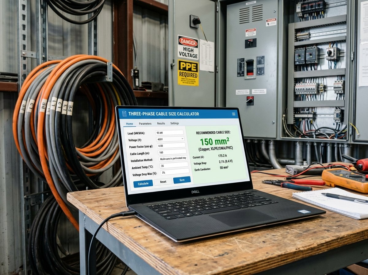
The Cable Size (Three-Phase) Calculator is a free online tool that calculates the recommended conductor size for three-phase circuits. It accounts for the load power or line current, power factor, line-to-line voltage, one-way cable length, maximum allowable voltage drop, and conductor material (copper or aluminium). It provides a clear breakdown of line current, load power, minimum cross-section based on voltage drop, recommended standard size, ampacity of the selected size, and actual voltage drop. The calculator is part of a suite of electrical and engineering calculators available on our website. For related calculations, you can use our Cable Size (Single-Phase) Calculator, Circuit Breaker Sizing Calculator, Backup Generator Sizing Calculator, and kW ↔ kVA Converter Calculator.
How to Use the Cable Size (Three-Phase) Calculator
Using the calculator is straightforward. Here’s a breakdown of each field:
1. Load
- Load input: Choose whether to enter the load as power (kW) or line current (A). Only the selected source is used.
- Load power: Enter the load power in kW. Used only when “Power (kW)” is selected.
- Line current: Enter the line current in A. Used only when “Line current (A)” is selected.
- Power factor: Enter the power factor. Typical values: 0.85–0.95 for motors, 1.0 for resistive loads. The default is 0.9.
2. Circuit
- Line-to-line voltage: Enter the nominal line-to-line voltage. The default is 400 V (common in Europe and many other regions). For 230 V phase-to-neutral, the line-to-line voltage is 400 V.
- One-way length: Enter the distance from the source to the load in meters or feet. This is the one-way length, not the total circuit length.
- Max voltage drop: Enter the maximum allowable voltage drop as a percentage. IEC recommends 5% for power circuits. The default is 5%.
3. Conductor
- Conductor material: Select Copper or Aluminium. Copper has lower resistivity and is more common for small cables. Aluminium is lighter and cheaper but requires a larger cross-section for the same current.
Once you enter all values, the calculator instantly displays:
- Line current (A)
- Load power (kW)
- Minimum cross-section based on voltage drop (mm²)
- Recommended standard size (mm²)
- Ampacity of selected size (A)
- Actual voltage drop (V)
- Drop percentage (%)
Understanding the Cost Components
To make the most of the calculator, it’s important to understand each component and how it affects cable sizing.
- Line current: The current flowing in each phase conductor. If you enter power in kW, the calculator computes current using the formula
I = (kW × 1000) / (√3 × V × PF). If you enter current directly, it uses that value. - Load power: If you enter current, the calculator computes power using
kW = √3 × V × I × PF / 1000. If you enter power, it uses that value. - Resistivity (ρ): The resistance of the conductor material per unit length and cross-section. Copper has ρ = 0.0175 Ω·mm²/m; aluminium has ρ = 0.0282 Ω·mm²/m. These values are at normal operating temperature.
- Allowed voltage drop (V): The maximum voltage drop in volts, calculated as
voltage × drop limit / 100. For example, 400 V × 5% = 20 V. - Minimum cross-section: The smallest conductor area that keeps voltage drop within the limit. For three-phase, the formula is derived from
ΔV = √3 × I × L × ρ / A, soA_min = √3 × ρ × I × L / ΔV. - Recommended size: The smallest standard cross-section that is greater than or equal to the minimum area. Standard sizes follow the IEC series: 1.5, 2.5, 4, 6, 10, 16, 25, 35, 50, 70, 95, 120, 150, 185, 240, 300 mm².
- Ampacity: The current-carrying capacity of the selected conductor size, based on typical installation with three loaded conductors in conduit. Copper and aluminium have different ampacity tables. The calculator shows the ampacity for reference—you should verify that it exceeds the design current.
- Actual voltage drop: The voltage drop with the recommended conductor size, calculated as
ΔV = √3 × I × L × ρ / A. The percentage isΔV / V × 100.
Understanding these components helps you select a cable that is safe, efficient, and compliant. For more information on cable sizing, you can refer to Wikipedia’s article on power cables.
Example Calculations
Let’s run through a few examples to see how the calculator works in different scenarios.
Example 1: 15 kW Motor, Copper Cable, 30 m Run
- Load input: Power (kW)
- Load power: 15 kW
- Power factor: 0.9
- Line-to-line voltage: 400 V
- One-way length: 30 m
- Max voltage drop: 5%
- Conductor material: Copper
Calculations:
- Line current: (15 × 1000) / (√3 × 400 × 0.9) = 24.06 A
- Load power: 15 kW
- Allowed voltage drop: 400 × 5% = 20 V
- Resistivity (Cu): 0.0175 Ω·mm²/m
- Minimum cross-section: (√3 × 0.0175 × 24.06 × 30) / 20 = 1.09 mm²
- Ampacity check: need a size with ampacity ≥ 24.06 A.
- Candidate sizes: 1.5 mm² (ampacity 15.5 A) – insufficient. 2.5 mm² (21 A) – insufficient. 4 mm² (28 A) – sufficient. Also meets area_min (4 ≥ 1.09).
- Recommended size: 4 mm²
- Ampacity of 4 mm² Cu (3-phase): 28 A
- Actual voltage drop: (√3 × 24.06 × 30 × 0.0175) / 4 = 5.46 V
- Drop percentage: 5.46 / 400 × 100 = 1.37%
- Recommended cable: 4 mm² copper
Example 2: 25 A Load, Aluminium Cable, 50 m Run
- Load input: Line current (A)
- Line current: 25 A
- Power factor: 0.9 (not used since current is entered)
- Line-to-line voltage: 400 V
- One-way length: 50 m
- Max voltage drop: 5%
- Conductor material: Aluminium
Calculations:
- Line current: 25 A
- Load power: √3 × 400 × 25 × 0.9 / 1000 = 15.59 kW
- Allowed voltage drop: 400 × 5% = 20 V
- Resistivity (Al): 0.0282 Ω·mm²/m
- Minimum cross-section: (√3 × 0.0282 × 25 × 50) / 20 = 3.05 mm²
- Ampacity check: need a size with ampacity ≥ 25 A.
- Candidate sizes: 4 mm² (ampacity 22 A) – insufficient. 6 mm² (28 A) – sufficient. Also meets area_min (6 ≥ 3.05).
- Recommended size: 6 mm²
- Ampacity of 6 mm² Al (3-phase): 28 A
- Actual voltage drop: (√3 × 25 × 50 × 0.0282) / 6 = 10.18 V
- Drop percentage: 10.18 / 400 × 100 = 2.55%
- Recommended cable: 6 mm² aluminium
Example 3: 30 kW Load, Copper Cable, 80 m Run
- Load input: Power (kW)
- Load power: 30 kW
- Power factor: 0.85
- Line-to-line voltage: 400 V
- One-way length: 80 m
- Max voltage drop: 5%
- Conductor material: Copper
Calculations:
- Line current: (30 × 1000) / (√3 × 400 × 0.85) = 50.94 A
- Load power: 30 kW
- Allowed voltage drop: 400 × 5% = 20 V
- Resistivity (Cu): 0.0175 Ω·mm²/m
- Minimum cross-section: (√3 × 0.0175 × 50.94 × 80) / 20 = 6.18 mm²
- Ampacity check: need a size with ampacity ≥ 50.94 A.
- Candidate sizes: 10 mm² (ampacity 50 A) – insufficient. 16 mm² (68 A) – sufficient. Also meets area_min (16 ≥ 6.18).
- Recommended size: 16 mm²
- Ampacity of 16 mm² Cu (3-phase): 68 A
- Actual voltage drop: (√3 × 50.94 × 80 × 0.0175) / 16 = 7.72 V
- Drop percentage: 7.72 / 400 × 100 = 1.93%
- Recommended cable: 16 mm² copper
These examples show how different loads, lengths, and materials affect cable sizing.
Benefits of Using the Cable Size (Three-Phase) Calculator
Tips for Accurate Cable Sizing
- Use the correct voltage drop limit: IEC recommends 5% for power circuits. Some local codes may require 3% or 4%. Always check your local regulations.
- Measure the one-way length accurately: The calculator uses the one-way distance from source to load. For three-phase, the voltage drop formula already accounts for the return path via the √3 factor.
- Choose the right conductor material: Copper has lower resistivity and is preferred for small cables. Aluminium is lighter and cheaper but requires a larger cross-section.
- Account for derating factors: Cable ampacity decreases when cables are bundled, run in hot environments, or installed in insulation. Apply derating factors from your local code.
- Verify ampacity: The calculator now automatically ensures the recommended size has sufficient ampacity. However, always double-check with the manufacturer’s data for your specific installation conditions.
- Consider future loads: If you plan to add more load later, size the cable for the future to avoid rewiring.
- Check the power factor: For motors and inductive loads, use the actual power factor (typically 0.85–0.95). Using 1.0 will underestimate the current.
- Use the correct resistivity: The calculator uses ρ = 0.0175 for copper and 0.0282 for aluminium at normal operating temperature. For precise calculations, adjust for the conductor temperature.
For more information on electrical installations, you can refer to resources like Wikipedia’s article on electrical wiring or guidelines from the International Electrotechnical Commission.
How to Reduce Voltage Drop
If your calculated voltage drop is too high, here are ways to reduce it:
- Increase cable size: A larger cross-section reduces resistance and voltage drop. This is the most common solution.
- Shorten the cable run: If possible, relocate the load closer to the source.
- Use copper instead of aluminium: Copper has lower resistivity, so it drops less voltage for the same size.
- Reduce the load: Lower current means lower voltage drop. If the load can be reduced, the drop decreases.
- Increase the voltage: In some cases, using a higher system voltage reduces current and voltage drop. This is not always practical.
- Use parallel conductors: Running two smaller cables in parallel increases the effective cross-section and reduces drop. This is common for large currents.
Frequently Asked Questions (FAQ)
Conclusion
The Cable Size (Three-Phase) Calculator is an essential tool for electricians, engineers, and anyone designing or modifying three-phase electrical circuits. It helps you determine the correct conductor size, verify voltage drop, and ensure safe, efficient, and code-compliant installations. By following the tips in this article and using the calculator, you can confidently select the right cable for your project. Don’t forget to explore our other electrical calculators for all your engineering needs.
Whether you’re wiring a new motor circuit or upgrading a distribution board, accurate cable sizing is key to a successful project. Try the Cable Size (Three-Phase) Calculator today and take the guesswork out of your electrical design.




3 Comments