Retaining Wall Design Calculator: Check Stability and Earth Pressure
Retaining walls hold back soil and prevent it from sliding or collapsing. They are used in gardens, driveways, basements, and infrastructure projects. Designing a retaining wall requires checking three main failure modes: overturning, sliding, and bearing pressure. An undersized wall can tip over, slide, or sink. An oversized wall wastes concrete and money. Our Retaining Wall Design Calculator is a free online tool that helps you quickly check the stability of a gravity or cantilever retaining wall based on its dimensions, soil properties, and loads.
In this guide, we’ll show you how to use the calculator, explain the calculations, provide real-world examples, and answer common questions. We’ll also share tips to ensure your retaining wall design is safe and efficient.
Retaining Wall Design
Construction CalculatorRetaining wall design: earth pressure, overturning, sliding and stability check.
What is the Retaining Wall Design Calculator?
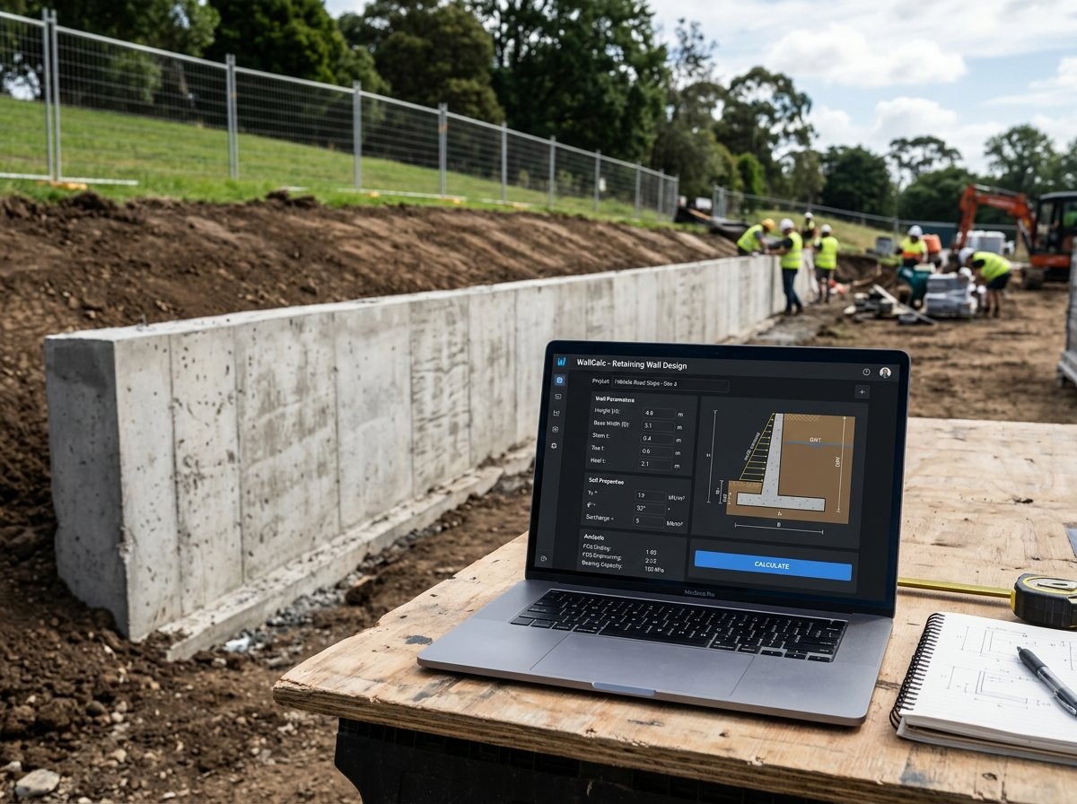
The Retaining Wall Design Calculator is a free online tool that calculates the active earth pressure, water pressure, surcharge forces, overturning moment, sliding resistance, and bearing pressure for a retaining wall. It supports different soil types (gravel, sand, silt, clay), wall materials (concrete, brick, block, stone, gabion), and allows for a water table and surcharge load. The calculator provides a clear breakdown of the active earth pressure coefficient, driving forces, stabilising weight, factors of safety against overturning and sliding, maximum bearing pressure, eccentricity, and an overall stability verdict. The tool is part of a suite of structural calculators available on our website. For related calculations, you can use our Beam Bending Moment Calculator, Column Axial Load Calculator, Padstone Design Calculator, and Lintel Sizing Calculator.
How to Use the Retaining Wall Design Calculator
Using the calculator is straightforward. Here’s a breakdown of each field:
1. Wall
- Retained height: Enter the height of soil to be retained in meters or feet.
- Base width: Enter the width of the wall base in meters or feet. Typically 0.5–0.7 × retained height for gravity walls.
- Stem thickness at base: Enter the thickness of the wall stem at its base in meters or inches. For example, 0.20 m = 200 mm.
2. Soil
- Backfill soil: Select the type of soil behind the wall: Gravel (φ = 36°, γ = 18 kN/m³), Sand (φ = 32°, γ = 18 kN/m³), Silt (φ = 28°, γ = 17 kN/m³), or Clay (φ = 22°, γ = 19 kN/m³). The angle of internal friction φ and unit weight γ are used to calculate earth pressure.
- Surcharge load: Enter any uniform load on top of the retained soil in kN/m². This could be from traffic, storage, or adjacent structures. The default is 0.
- Water table depth: Enter the depth below the top of the retained soil where the water table is located, in meters or feet. Set a large value (e.g., 10) if no water table is present. Water pressure adds to the driving forces.
3. Wall material
- Wall material: Select the material: Mass concrete (γ = 24 kN/m³), Brick masonry (γ = 20 kN/m³), Block masonry (γ = 20 kN/m³), Stone (γ = 24 kN/m³), or Gabion (γ = 18 kN/m³). The unit weight affects the stabilising weight.
4. Foundation
- Foundation depth: Enter the depth of the foundation below the base of the wall in meters or feet.
- Foundation width: Enter the width of the foundation in meters or feet. Usually wider than the wall base to spread the bearing pressure.
- Allowable soil bearing: Enter the allowable bearing pressure of the soil in kN/m². Typical values are 100–300 kN/m². Check local geotechnical data.
Once you enter all values, the calculator instantly displays:
- Active earth pressure coefficient (Ka)
- Internal friction angle (φ)
- Earth pressure force (kN/m)
- Surcharge force (kN/m)
- Water pressure force (kN/m) – if applicable
- Total driving force (kN/m)
- Total stabilising weight (kN/m)
- Factor of safety against overturning (with OK/FAIL)
- Factor of safety against sliding (with OK/FAIL)
- Maximum bearing pressure (kN/m²) with OK/FAIL
- Eccentricity (m)
- Overall stability verdict
Understanding the Cost Components
To make the most of the calculator, it’s important to understand each output and the underlying formulas.
- Active earth pressure coefficient (Ka): A coefficient that relates the vertical effective stress to the horizontal earth pressure. It is calculated using Rankine’s theory:
Ka = (1 - sin φ) / (1 + sin φ). Higher φ means lower Ka, so granular soils (gravel, sand) exert less pressure than clay. - Earth pressure force (F_earth): The total horizontal force from the soil, calculated as
0.5 × Ka × γ_soil × H²per metre of wall. It acts at one-third of the height from the base. - Surcharge force (F_surcharge): The additional horizontal force from a uniform surcharge on top of the soil:
Ka × surcharge × H. It acts at mid-height. - Water pressure force (F_water): If the water table is above the base, hydrostatic pressure adds to the driving force:
0.5 × γ_w × h_w², whereh_wis the height of water above the base. It acts at one-third of the water height. - Total driving force (F_h): The sum of earth pressure, surcharge, and water forces.
- Overturning moment (M_overturn): The moment of the driving forces about the front toe of the wall:
F_earth × H/3 + F_surcharge × H/2 + F_water × h_w/3. - Stabilising weight (W_total): The sum of the weights of the stem, foundation, and soil on the heel. The stem weight is
H × stem_t × γ_wall. The foundation weight isfound_w × found_d × γ_wall. The heel soil weight isH × heel_width × γ_soil, where heel width isfound_w - stem_t(assuming the stem is at the front edge). - Restoring moment (M_restore): The moment of the stabilising weights about the front toe:
W_stem × x_stem + W_base × x_base + W_heel × x_heel, where the lever arms are measured from the front toe. - Factor of safety against overturning:
FoS_overturn = M_restore / M_overturn. A value of 1.5 or greater is typically required. - Sliding resistance:
F_resist = W_total × μ, whereμ = tan φis the coefficient of friction between the base and soil.FoS_slide = F_resist / F_h. A value of 1.5 or greater is typically required. - Eccentricity (e): The distance from the centre of the foundation to the point where the resultant force acts. It is calculated as
e = (found_w / 2) - ((M_restore - M_overturn) / W_total). If e exceedsfound_w / 6, the bearing pressure becomes triangular with a zero or negative value at the heel, which is usually unacceptable. - Bearing pressure: The maximum and minimum pressures under the foundation:
q_max = (W_total / found_w) × (1 + 6e / found_w),q_min = (W_total / found_w) × (1 - 6e / found_w). The maximum must not exceed the allowable soil bearing pressure.
Understanding these components helps you interpret the results and adjust your design. For more information on retaining wall design, you can refer to Wikipedia’s article on retaining walls.
Example Calculations
Let’s run through a few examples to see how the calculator works in different scenarios.
Example 1: Gravity Wall, Sand Backfill, No Water
- Retained height: 1.2 m
- Base width: 0.6 m
- Stem thickness: 0.20 m
- Backfill soil: Sand (φ = 32°, γ = 18 kN/m³)
- Surcharge: 0 kN/m²
- Water table depth: 10 m (no water)
- Wall material: Mass concrete (γ = 24 kN/m³)
- Foundation depth: 0.30 m
- Foundation width: 0.80 m
- Allowable bearing: 200 kN/m²
Calculations:
- Ka = (1 – sin 32°) / (1 + sin 32°) = (1 – 0.530) / (1 + 0.530) = 0.470 / 1.530 = 0.307
- p_earth = 0.307 × 18 × 1.2 = 6.63 kN/m²
- F_earth = 0.5 × 6.63 × 1.2 = 3.98 kN/m, h_earth = 0.4 m
- F_surcharge = 0, F_water = 0
- F_h = 3.98 kN/m
- M_overturn = 3.98 × 0.4 = 1.59 kN·m/m
- Stem weight = 1.2 × 0.20 × 24 = 5.76 kN/m
- Base weight = 0.80 × 0.30 × 24 = 5.76 kN/m
- Heel width = 0.80 – 0.20 = 0.60 m
- Heel soil weight = 1.2 × 0.60 × 18 = 12.96 kN/m
- W_total = 5.76 + 5.76 + 12.96 = 24.48 kN/m
- x_stem = 0.20 / 2 = 0.10 m
- x_base = 0.80 / 2 = 0.40 m
- x_heel = 0.80 – 0.60 / 2 = 0.50 m
- M_restore = 5.76×0.10 + 5.76×0.40 + 12.96×0.50 = 0.576 + 2.304 + 6.48 = 9.36 kN·m/m
- FoS_overturn = 9.36 / 1.59 = 5.89 (OK ≥ 1.5)
- μ = tan 32° = 0.625
- F_resist = 24.48 × 0.625 = 15.30 kN/m
- FoS_slide = 15.30 / 3.98 = 3.84 (OK ≥ 1.5)
- e = (0.80/2) – ((9.36 – 1.59)/24.48) = 0.40 – (7.77/24.48) = 0.40 – 0.317 = 0.083 m
- bearing_max = (24.48/0.80) × (1 + 6×0.083/0.80) = 30.6 × (1 + 0.6225) = 30.6 × 1.6225 = 49.65 kN/m² (OK ≤ 200)
- Overall: STABLE
Example 2: Cantilever Wall, Clay Backfill, Surcharge, Water Table
- Retained height: 2.5 m
- Base width: 1.5 m
- Stem thickness: 0.25 m
- Backfill soil: Clay (φ = 22°, γ = 19 kN/m³)
- Surcharge: 10 kN/m²
- Water table depth: 1.5 m (so water height = 2.5 – 1.5 = 1.0 m)
- Wall material: Concrete (γ = 24 kN/m³)
- Foundation depth: 0.40 m
- Foundation width: 2.0 m
- Allowable bearing: 150 kN/m²
Calculations:
- Ka = (1 – sin 22°) / (1 + sin 22°) = (1 – 0.375) / (1 + 0.375) = 0.625 / 1.375 = 0.455
- p_earth = 0.455 × 19 × 2.5 = 21.61 kN/m²
- F_earth = 0.5 × 21.61 × 2.5 = 27.01 kN/m, h_earth = 0.833 m
- p_surcharge = 0.455 × 10 = 4.55 kN/m²
- F_surcharge = 4.55 × 2.5 = 11.38 kN/m, h_surcharge = 1.25 m
- p_water = 9.81 × 1.0 = 9.81 kN/m²
- F_water = 0.5 × 9.81 × 1.0 = 4.905 kN/m, h_water = 0.333 m
- F_h = 27.01 + 11.38 + 4.905 = 43.30 kN/m
- M_overturn = 27.01×0.833 + 11.38×1.25 + 4.905×0.333 = 22.50 + 14.23 + 1.63 = 38.36 kN·m/m
- Stem weight = 2.5 × 0.25 × 24 = 15.0 kN/m
- Base weight = 2.0 × 0.40 × 24 = 19.2 kN/m
- Heel width = 2.0 – 0.25 = 1.75 m
- Heel soil weight = 2.5 × 1.75 × 19 = 83.13 kN/m
- W_total = 15.0 + 19.2 + 83.13 = 117.33 kN/m
- x_stem = 0.25 / 2 = 0.125 m
- x_base = 2.0 / 2 = 1.0 m
- x_heel = 2.0 – 1.75 / 2 = 1.125 m
- M_restore = 15.0×0.125 + 19.2×1.0 + 83.13×1.125 = 1.875 + 19.2 + 93.52 = 114.60 kN·m/m
- FoS_overturn = 114.60 / 38.36 = 2.99 (OK ≥ 1.5)
- μ = tan 22° = 0.404
- F_resist = 117.33 × 0.404 = 47.40 kN/m
- FoS_slide = 47.40 / 43.30 = 1.09 (FAILS < 1.5)
- e = (2.0/2) – ((114.60 – 38.36)/117.33) = 1.0 – (76.24/117.33) = 1.0 – 0.650 = 0.350 m
- bearing_max = (117.33/2.0) × (1 + 6×0.350/2.0) = 58.67 × (1 + 1.05) = 58.67 × 2.05 = 120.27 kN/m² (OK ≤ 150)
- Overall: UNSTABLE (sliding fails)
Example 3: Gabion Wall, Gravel Backfill, High Water Table
- Retained height: 1.8 m
- Base width: 1.0 m
- Stem thickness: 1.0 m (gabion wall is a single block)
- Backfill soil: Gravel (φ = 36°, γ = 18 kN/m³)
- Surcharge: 0
- Water table depth: 0.5 m (water height = 1.3 m)
- Wall material: Gabion (γ = 18 kN/m³)
- Foundation depth: 0.3 m
- Foundation width: 1.2 m
- Allowable bearing: 250 kN/m²
Calculations:
- Ka = (1 – sin 36°) / (1 + sin 36°) = (1 – 0.588) / (1 + 0.588) = 0.412 / 1.588 = 0.259
- p_earth = 0.259 × 18 × 1.8 = 8.39 kN/m²
- F_earth = 0.5 × 8.39 × 1.8 = 7.55 kN/m, h_earth = 0.6 m
- F_surcharge = 0
- p_water = 9.81 × 1.3 = 12.75 kN/m²
- F_water = 0.5 × 12.75 × 1.3 = 8.29 kN/m, h_water = 0.433 m
- F_h = 7.55 + 8.29 = 15.84 kN/m
- M_overturn = 7.55×0.6 + 8.29×0.433 = 4.53 + 3.59 = 8.12 kN·m/m
- Stem weight = 1.8 × 1.0 × 18 = 32.4 kN/m (gabion is thick)
- Base weight = 1.2 × 0.3 × 18 = 6.48 kN/m
- Heel width = 1.2 – 1.0 = 0.2 m
- Heel soil weight = 1.8 × 0.2 × 18 = 6.48 kN/m
- W_total = 32.4 + 6.48 + 6.48 = 45.36 kN/m
- x_stem = 1.0 / 2 = 0.5 m
- x_base = 1.2 / 2 = 0.6 m
- x_heel = 1.2 – 0.2/2 = 1.1 m
- M_restore = 32.4×0.5 + 6.48×0.6 + 6.48×1.1 = 16.2 + 3.888 + 7.128 = 27.216 kN·m/m
- FoS_overturn = 27.216 / 8.12 = 3.35 (OK)
- μ = tan 36° = 0.727
- F_resist = 45.36 × 0.727 = 32.98 kN/m
- FoS_slide = 32.98 / 15.84 = 2.08 (OK ≥ 1.5)
- e = (1.2/2) – ((27.216 – 8.12)/45.36) = 0.6 – (19.096/45.36) = 0.6 – 0.421 = 0.179 m
- bearing_max = (45.36/1.2) × (1 + 6×0.179/1.2) = 37.8 × (1 + 0.895) = 37.8 × 1.895 = 71.63 kN/m² (OK ≤ 250)
- Overall: STABLE
These examples show how different soil types, water tables, and wall geometries affect stability.
Benefits of Using the Retaining Wall Design Calculator
Tips for Accurate Retaining Wall Design
- Determine soil properties accurately: The angle of internal friction and unit weight are critical. Use local geotechnical data if available. If not, use conservative values.
- Account for water: Water pressure can double the driving force. If the water table is high, provide drainage behind the wall (e.g., gravel backfill and weep holes) to reduce pressure.
- Consider surcharge: Traffic, storage, or adjacent structures add load. Include them in the design.
- Check sliding: Sliding is often the governing failure mode. You can increase resistance by adding a key, increasing the base width, or using a rougher base.
- Check bearing: Ensure the maximum bearing pressure does not exceed the allowable soil bearing. If it does, widen the foundation or improve the soil.
- Check eccentricity: Keep the resultant within the middle third of the base (
e ≤ found_w / 6) to avoid tension under the heel. - Use the correct wall material density: Concrete and stone are heavier than brick or gabion, which affects stability.
- Verify with a professional: For any structural work, have a qualified engineer verify your calculations and ensure compliance with local building codes.
For more information on retaining wall design, you can refer to resources like Wikipedia’s article on retaining walls or guidelines from the Institution of Structural Engineers.
How to Improve Retaining Wall Stability
If your wall fails any check, here are ways to improve stability:
- Increase base width: A wider base increases the restoring moment and reduces bearing pressure.
- Add a heel: Extending the foundation behind the stem increases the weight of soil on the heel, improving overturning and sliding resistance.
- Add a key: A shear key at the base increases sliding resistance.
- Improve drainage: Reduce water pressure by installing drainage behind the wall.
- Use heavier material: Concrete or stone instead of brick or gabion increases stabilising weight.
- Reduce retained height: A lower wall exerts less earth pressure.
- Reinforce the soil: Use geogrids to increase the effective friction angle and reduce earth pressure.
Frequently Asked Questions (FAQ)
Conclusion
The Retaining Wall Design Calculator is an essential tool for builders, landscapers, engineers, and DIY enthusiasts. It helps you check the stability of a retaining wall against overturning, sliding, and bearing failure. By following the tips in this article and using the calculator, you can confidently design a safe and efficient retaining wall. Don’t forget to explore our other structural calculators for all your design needs.
Whether you’re building a small garden wall or a large basement retaining wall, accurate stability analysis is key to a successful project. Try the Retaining Wall Design Calculator today and take the guesswork out of your structural design.