

Column Axial Load Calculator: Check Buckling and Squash Capacity
Columns are the vertical members that carry loads from beams, slabs, and roofs down to the foundations. Unlike beams, which primarily resist bending, columns are subjected to axial compression. Their design is governed by two main failure modes: yielding (squash) and buckling. An undersized column can buckle suddenly, leading to catastrophic collapse. An oversized column wastes material and increases cost. Our Column Axial Load Calculator is a free online tool that helps you quickly determine the Euler buckling load, squash load, governing capacity, slenderness ratio, and utilisation for steel, timber, or concrete columns.
In this guide, we’ll show you how to use the calculator, explain the calculations, provide real-world examples, and answer common questions. We’ll also share tips to ensure your column design is safe and efficient.
Column Axial Load
Construction CalculatorColumn axial load capacity: buckling (Euler) and squash check for steel or timber.
What is the Column Axial Load Calculator?
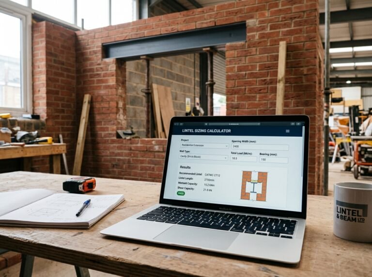
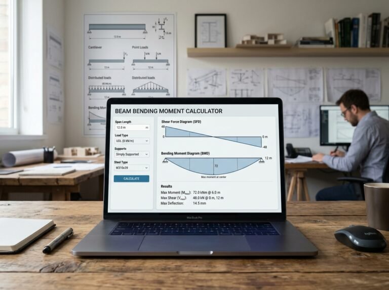
The Column Axial Load Calculator is a free online tool that calculates the axial load capacity of a column based on its effective length, cross-section dimensions, end conditions, material properties, and applied load. It supports pinned-pinned, fixed-fixed, fixed-pinned, and fixed-free end conditions. Materials include steel, timber, concrete, or custom values. The calculator provides a clear breakdown of the effective length factor K, effective length, cross-sectional area, moment of inertia (weak axis), radius of gyration, slenderness ratio, Euler critical load, squash load, governing capacity, applied load, utilisation, and a pass/fail status. The tool is part of a suite of structural calculators available on our website. For related calculations, you can use our Beam Bending Moment Calculator, Floor Joist Sizing Calculator, Steel Beam (UB) Selection Calculator, and Lintel Sizing Calculator.
How to Use the Column Axial Load Calculato
Using the calculator is straightforward. Here’s a breakdown of each field:
1. Column
- Effective length: Enter the effective length of the column in meters or feet. If you have already applied the K factor, enter the effective length directly. Otherwise, enter the physical length and select the end conditions below; the calculator will apply K.
- Section width: Enter the width of the rectangular cross-section in meters or inches. For example, 0.1 m = 100 mm.
- Section depth: Enter the depth of the rectangular cross-section in meters or inches. For example, 0.1 m = 100 mm.
2. Support
- End conditions: Select the end conditions from the dropdown: Pinned–pinned (K = 1.0), Fixed–fixed (K = 0.5), Fixed–pinned (K = 0.7), or Fixed–free (K = 2.0). The K factor multiplies the effective length used in the Euler calculation.
3. Material
- Material: Select Steel (E = 210 GPa, fy = 275 MPa), Timber (E = 10 GPa, fc = 22 MPa), Concrete (E = 30 GPa, fc = 30 MPa), or Custom. Presets are typical values—override below for exact grade.
- Young’s modulus: If you selected “Custom”, enter the modulus of elasticity in GPa.
- Yield / compressive strength: If you selected “Custom”, enter the yield strength (for steel) or compressive strength (for timber/concrete) in N/mm².
4. Load
- Applied axial load: Enter the applied axial load in kN. Set to 0 to skip the utilisation check and only see the capacity.
Once you enter all values, the calculator instantly displays:
- Effective length factor K
- Effective length (m)
- Cross-section area (mm²)
- Moment of inertia (weak axis, mm⁴)
- Radius of gyration (mm)
- Slenderness ratio
- Euler critical load (kN)
- Squash load (kN)
- Governing capacity (kN)
- Applied load (kN) – if entered
- Utilisation (%)
- Status (Column OK or Column overloaded)
Understanding the Cost Components
To make the most of the calculator, it’s important to understand each output and the underlying formulas.
- Effective length factor K: A coefficient that depends on the end conditions. It accounts for the fact that a column’s buckling length differs from its physical length. Values: pinned-pinned 1.0, fixed-fixed 0.5, fixed-pinned 0.7, fixed-free 2.0.
- Effective length (L_eff): The length used in the Euler buckling formula:
L_eff = K × L, where L is the physical length. If you enter an effective length directly, the calculator uses that value and K is not applied again. - Cross-section area (A):
A = b × d, where b is width and d is depth. It is used to calculate the squash load. - Moment of inertia (I): For a rectangular section,
I_x = b × d³ / 12andI_y = d × b³ / 12. The calculator uses the smaller of the two (weak axis) because buckling occurs about the weak axis. - Radius of gyration (r):
r = √(I / A). It represents how far the material is distributed from the centroid. A larger r means a more efficient column. - Slenderness ratio (λ):
λ = L_eff / r. It indicates how prone the column is to buckling. Higher values mean more slender and more likely to buckle elastically. - Euler critical load (P_cr): The load at which elastic buckling occurs:
P_cr = π² E I / L_eff². It depends on the material’s modulus of elasticity E, the moment of inertia I, and the effective length. - Squash load (P_squash): The load at which the material yields or crushes:
P_squash = A × fy, where fy is the yield strength (steel) or compressive strength (timber/concrete). - Governing capacity (P_gov): The smaller of P_cr and P_squash. This is a simplified approach; in reality, column design uses interaction formulas (e.g., Perry-Robertson) to account for the transition between buckling and yielding. For preliminary sizing, the min() rule is conservative.
- Utilisation:
applied load / governing capacity. If ≤ 1.0, the column is adequate (Column OK). If > 1.0, it is overloaded.
Understanding these components helps you interpret the results and adjust your design. For more information on column buckling, you can refer to Wikipedia’s article on buckling.
Example Calculations
Let’s run through a few examples to see how the calculator works in different scenarios.
Example 1: Steel Column, Pinned-Pinned, 3 m Physical Length
- Physical length: 3 m
- Section width: 0.1 m (100 mm)
- Section depth: 0.1 m (100 mm)
- End conditions: Pinned–pinned (K = 1.0)
- Material: Steel (E = 210 GPa, fy = 275 MPa)
- Applied load: 100 kN
Calculations:
- K = 1.0
- L_eff = 3000 × 1.0 = 3000 mm
- A = 100 × 100 = 10,000 mm²
- I_x = 100 × 100³ / 12 = 8,333,333 mm⁴; I_y = same (square)
- Weak axis I = 8,333,333 mm⁴
- r = √(8,333,333 / 10,000) = 28.87 mm
- Slenderness = 3000 / 28.87 = 103.9
- P_cr = π² × 210,000 × 8,333,333 / 3000² = 1,916,000 N ≈ 1,916 kN
- P_squash = 10,000 × 275 = 2,750,000 N = 2,750 kN
- Governing capacity = min(1916, 2750) = 1916 kN
- Utilisation = 100 / 1916 = 5.2%
- Result: Capacity 1916 kN, OK
Example 2: Timber Column, Fixed-Pinned, 2 m Physical Length
- Physical length: 2 m
- Section width: 0.15 m (150 mm)
- Section depth: 0.15 m (150 mm)
- End conditions: Fixed–pinned (K = 0.7)
- Material: Timber (E = 10 GPa, fc = 22 MPa)
- Applied load: 50 kN
Calculations:
- L_eff = 2000 × 0.7 = 1400 mm
- A = 150 × 150 = 22,500 mm²
- I = 150 × 150³ / 12 = 42,187,500 mm⁴
- r = √(42,187,500 / 22,500) = 43.30 mm
- Slenderness = 1400 / 43.30 = 32.3
- P_cr = π² × 10,000 × 42,187,500 / 1400² = 2,124,000 N ≈ 2,124 kN
- P_squash = 22,500 × 22 = 495,000 N = 495 kN
- Governing capacity = min(2124, 495) = 495 kN
- Utilisation = 50 / 495 = 10.1%
- Result: Capacity 495 kN, OK
Example 3: Concrete Column, Fixed-Free, 4 m Physical Length
- Physical length: 4 m
- Section width: 0.2 m (200 mm)
- Section depth: 0.2 m (200 mm)
- End conditions: Fixed–free (K = 2.0)
- Material: Concrete (E = 30 GPa, fc = 30 MPa)
- Applied load: 200 kN
Calculations:
- L_eff = 4000 × 2.0 = 8000 mm
- A = 200 × 200 = 40,000 mm²
- I = 200 × 200³ / 12 = 133,333,333 mm⁴
- r = √(133,333,333 / 40,000) = 57.74 mm
- Slenderness = 8000 / 57.74 = 138.6
- P_cr = π² × 30,000 × 133,333,333 / 8000² = 617,000 N ≈ 617 kN
- P_squash = 40,000 × 30 = 1,200,000 N = 1,200 kN
- Governing capacity = min(617, 1200) = 617 kN
- Utilisation = 200 / 617 = 32.4%
- Result: Capacity 617 kN, OK
These examples show how different end conditions, materials, and section sizes affect the column capacity.
Benefits of Using the Column Axial Load Calculator
Tips for Accurate Column Analysis
- Enter the physical length, not the effective length: The calculator automatically applies the K factor from the end conditions. If you have already multiplied by K, divide by K before entering, or select K = 1.0 (pinned-pinned).
- Choose the correct end conditions: End conditions depend on how the column is connected. Pinned-pinned is common for simple connections. Fixed-fixed is for rigid connections. Fixed-pinned is a combination. Fixed-free is for cantilever columns. If unsure, use pinned-pinned (K = 1.0) as a conservative default.
- Check both axes: The calculator uses the weak axis for buckling. If your column is restrained about one axis, you may need to check the other axis separately.
- Use realistic material properties: Steel, timber, and concrete have different strengths and stiffnesses. If you’re using a specific grade, select “Custom” and enter the correct values.
- Apply safety factors: The calculator gives ultimate capacity. Design codes require safety factors (e.g., 1.5–2.0 for steel). Always apply the appropriate factor of safety.
- Consider eccentricity: The calculator assumes pure axial load. In reality, loads may be eccentric, causing bending. For eccentric loads, use a beam-column interaction formula.
- Check slenderness limits: Very slender columns may be governed by elastic buckling, while stocky columns may be governed by yielding. The slenderness ratio helps you understand which mode governs.
- Verify with a professional: For critical structures, have a qualified structural engineer verify your design.
For more information on column design, you can refer to resources like Wikipedia’s article on columns or guidelines from the American Institute of Steel Construction.
How to Increase Column Capacity
If your column is overloaded, here are ways to increase its capacity:
- Increase cross-section dimensions: A larger area increases squash load and moment of inertia, boosting both buckling and yielding capacity.
- Reduce effective length: Adding lateral bracing or changing end conditions reduces K, which increases the Euler critical load.
- Use a stronger material: Higher yield strength increases squash load; higher modulus of elasticity increases buckling load.
- Change the section shape: A hollow or I-shaped section has a higher moment of inertia for the same area, improving buckling resistance.
- Add intermediate supports: Reducing the unbraced length directly reduces slenderness and increases capacity.
- Use composite construction: Combining steel and concrete can significantly increase capacity.
Frequently Asked Questions (FAQ)
Conclusion
The Column Axial Load Calculator is an essential tool for structural engineers, architects, builders, and students. It helps you quickly determine buckling and squash capacities, slenderness ratios, and utilisation for common column configurations. By following the tips in this article and using the calculator, you can confidently analyze your columns. Don’t forget to explore our other structural calculators for all your design needs.
Whether you’re designing a simple timber post or a steel column in a multi-story building, accurate axial load analysis is key to a safe and efficient structure. Try the Column Axial Load Calculator today and take the guesswork out of your structural calculations.




3 Comments