
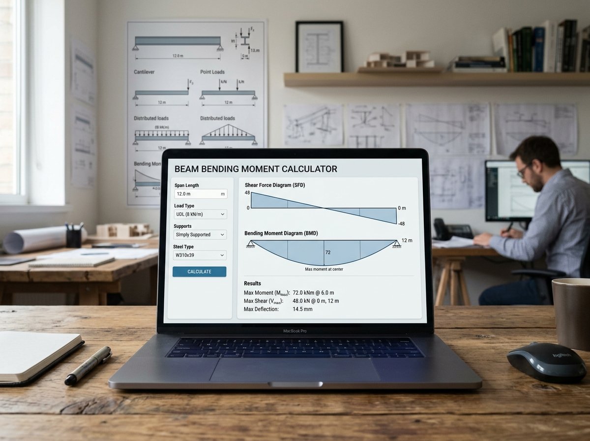
Beam Bending Moment Calculator: Analyze Moments, Shear, and Deflection
Beam design is a cornerstone of structural engineering. Whether you’re sizing a floor joist, a lintel, or a steel beam, you need to know the bending moment, shear force, and deflection under load. Our Beam Bending Moment Calculator is a free online tool that helps you quickly analyze simply supported, cantilever, and fixed-end beams under point loads or uniformly distributed loads (UDL). It provides a clear breakdown of section properties, maximum bending moment, shear force, bending stress, and deflection, along with a check against your specified deflection limit.
In this guide, we’ll show you how to use the calculator, explain the calculations, provide real-world examples, and answer common questions. We’ll also share tips to ensure your beam analysis is accurate and safe.
Beam Bending Moment
Construction CalculatorBeam bending moment and deflection: point or UDL, simply supported or cantilever.
What is the Beam Bending Moment Calculator?
The Beam Bending Moment Calculator is a free online tool that calculates the internal forces and deflection of a beam based on its span, cross-section, support conditions, load type, and material properties. It supports three support types: simply supported, cantilever, and fixed both ends. Load types include point load at mid-span, uniformly distributed load (UDL), and point load at a specified distance (for simply supported beams only). The calculator also computes section properties (moment of inertia and section modulus) and checks deflection against a user-defined limit (e.g., L/360). The tool is part of a suite of structural calculators available on our website. For related calculations, you can use our Steel Beam (UB) Selection Calculator, Floor Joist Sizing Calculator, Column Axial Load Calculator, and Lintel Sizing Calculator.
How to Use the Beam Bending Moment Calculator
Using the calculator is straightforward. Here’s a breakdown of each field:
1. Beam
- Beam span: Enter the clear span of the beam in meters or feet. This is the distance between supports (for simply supported and fixed) or the length of the cantilever.
- Section width: Enter the width of the rectangular cross-section in meters or inches. For example, 0.1 m = 100 mm.
- Section depth: Enter the depth of the rectangular cross-section in meters or inches. For example, 0.2 m = 200 mm.
2. Support
- Support type: Select Simply supported, Cantilever, or Fixed both ends. The support conditions determine the moment and deflection formulas.
3. Load
- Load type: Select Point load (mid-span), Uniformly distributed (UDL), or Point load at distance (simply supported only). For cantilevers, point loads are always taken at the free end.
- Total load: Enter the total load in kN. For a UDL, this is the total load over the span (e.g., 10 kN total). For a point load, this is the single load value.
- Point-load position: If you selected “Point load at distance”, enter the distance from the left support in meters or feet. This field is ignored for other load types.
4. Material
- Material: Select Steel (E = 210 GPa), Timber (E = 10 GPa), Concrete (E = 30 GPa), or Custom Young’s modulus. The modulus of elasticity affects deflection.
- Young’s modulus: If you selected “Custom”, enter the modulus in GPa.
- Deflection limit: Enter the deflection limit as a divisor of the span. For example, 360 gives L/360. Common limits are L/240, L/360, and L/480.
Once you enter all values, the calculator instantly displays:
- Moment of inertia (I)
- Section modulus (Z)
- Max bending moment (kN·m)
- Max shear force (kN)
- Bending stress (N/mm²)
- Max deflection (mm)
- Deflection limit (mm)
- Deflection status (OK or exceeds limit)
Understanding the Cost Components
To make the most of the calculator, it’s important to understand each output and the underlying formulas.
- Moment of inertia (I): A geometric property of the cross-section that measures its resistance to bending. For a rectangular section,
I = b × d³ / 12. It is calculated in mm⁴. - Section modulus (Z): The ratio of moment of inertia to the distance from the neutral axis to the extreme fiber. For a rectangle,
Z = b × d² / 6. It is used to calculate bending stress:σ = M / Z. - Max bending moment (M): The maximum internal moment in the beam. It depends on support and load type:
- Simply supported, UDL:
M = wL² / 8 - Simply supported, point load at mid-span:
M = PL / 4 - Simply supported, point load at distance a:
M = P·a·b / L - Cantilever, UDL:
M = wL² / 2 - Cantilever, point load at free end:
M = PL - Fixed both ends, UDL:
M = wL² / 12 - Fixed both ends, point load at mid-span:
M = PL / 8
- Simply supported, UDL:
- Max shear force (V): The maximum internal shear. For simply supported UDL:
V = wL/2. For point load:V = P·max(a,b)/L. For cantilever:V = wLorP. For fixed:V = wL/2orP/2. - Bending stress (σ): The maximum stress in the beam due to bending:
σ = M / Z. It is compared to the material’s allowable stress (not checked by this calculator; you must verify against code). - Max deflection (δ): The maximum vertical displacement. Formulas depend on support and load:
- Simply supported, UDL:
δ = 5wL⁴ / (384EI) - Simply supported, point load at mid-span:
δ = PL³ / (48EI) - Simply supported, point load at distance:
δ = P·a²·b² / (3EI·L) - Cantilever, UDL:
δ = wL⁴ / (8EI) - Cantilever, point load:
δ = PL³ / (3EI) - Fixed both ends, UDL:
δ = wL⁴ / (384EI) - Fixed both ends, point load at mid-span:
δ = PL³ / (192EI)
- Simply supported, UDL:
- Deflection limit: A serviceability criterion, often expressed as a fraction of the span (e.g., L/360). The calculator compares the actual deflection to this limit.
Understanding these components helps you interpret the results and adjust your design. For more information on beam theory, you can refer to Wikipedia’s article on bending.
Example Calculations
Let’s run through a few examples to see how the calculator works in different scenarios.
Example 1: Simply Supported Beam with UDL
- Span: 4 m
- Width: 0.1 m (100 mm)
- Depth: 0.2 m (200 mm)
- Support: Simply supported
- Load type: UDL
- Total load: 10 kN
- Material: Steel (E = 210 GPa)
- Deflection limit: L/360
Calculations:
- Section properties: I = 100 × 200³ / 12 = 66,666,667 mm⁴; Z = 100 × 200² / 6 = 666,667 mm³
- w = 10 kN / 4 m = 2.5 kN/m = 2.5 N/mm
- Max moment: wL² / 8 = 2.5 × 4000² / 8 = 5,000,000 N·mm = 5 kN·m
- Max shear: wL / 2 = 2.5 × 4000 / 2 = 5,000 N = 5 kN
- Bending stress: 5,000,000 / 666,667 = 7.5 N/mm²
- Max deflection: 5wL⁴ / (384EI) = 5 × 2.5 × 4000⁴ / (384 × 210,000 × 66,666,667) = 5.96 mm
- Deflection limit: 4000 / 360 = 11.11 mm
- Deflection OK
- Result: M = 5 kN·m, V = 5 kN, σ = 7.5 N/mm², δ = 5.96 mm (OK)
Example 2: Cantilever with Point Load at Free End
- Span: 2 m (cantilever length)
- Width: 0.1 m
- Depth: 0.2 m
- Support: Cantilever
- Load type: Point load (at free end)
- Total load: 5 kN
- Material: Steel (E = 210 GPa)
- Deflection limit: L/240
Calculations:
- I = 66,666,667 mm⁴; Z = 666,667 mm³
- Max moment: PL = 5,000 × 2000 = 10,000,000 N·mm = 10 kN·m
- Max shear: P = 5,000 N = 5 kN
- Bending stress: 10,000,000 / 666,667 = 15 N/mm²
- Max deflection: PL³ / (3EI) = 5,000 × 2000³ / (3 × 210,000 × 66,666,667) = 9.52 mm
- Deflection limit: 2000 / 240 = 8.33 mm
- Deflection exceeds limit
- Result: M = 10 kN·m, V = 5 kN, σ = 15 N/mm², δ = 9.52 mm (exceeds L/240)
Example 3: Fixed Both Ends with UDL
- Span: 6 m
- Width: 0.15 m (150 mm)
- Depth: 0.3 m (300 mm)
- Support: Fixed both ends
- Load type: UDL
- Total load: 20 kN
- Material: Concrete (E = 30 GPa)
- Deflection limit: L/360
Calculations:
- I = 150 × 300³ / 12 = 337,500,000 mm⁴; Z = 150 × 300² / 6 = 2,250,000 mm³
- w = 20 kN / 6 m = 3.333 kN/m = 3.333 N/mm
- Max moment: wL² / 12 = 3.333 × 6000² / 12 = 10,000,000 N·mm = 10 kN·m
- Max shear: wL / 2 = 3.333 × 6000 / 2 = 10,000 N = 10 kN
- Bending stress: 10,000,000 / 2,250,000 = 4.44 N/mm²
- Max deflection: wL⁴ / (384EI) = 3.333 × 6000⁴ / (384 × 30,000 × 337,500,000) = 1.11 mm
- Deflection limit: 6000 / 360 = 16.67 mm
- Deflection OK
- Result: M = 10 kN·m, V = 10 kN, σ = 4.44 N/mm², δ = 1.11 mm (OK)
These examples show how different support conditions, load types, and materials affect the results.
Benefits of Using the Beam Bending Moment Calculator
Tips for Accurate Beam Analysis
- Use consistent units: The calculator handles unit conversions internally, but ensure you enter values in the selected units (meters or feet/inches). The primary unit for length is meters.
- Choose the correct support condition: Simply supported, cantilever, and fixed ends have very different moment and deflection formulas. Selecting the wrong support will give incorrect results.
- Select the right load type: UDL and point loads behave differently. For a point load not at mid-span, use “Point load at distance” (simply supported only).
- Enter the total load correctly: For a UDL, enter the total load over the entire span, not the load per meter. The calculator converts it to a distributed load internally.
- Use realistic material properties: Steel, timber, and concrete have different moduli of elasticity. If you’re using a different material, select “Custom” and enter its E value.
- Check deflection limits: Deflection limits are serviceability criteria. Common limits are L/240 for roofs, L/360 for floors, and L/480 for sensitive equipment. Always verify with local codes.
- Verify bending stress: The calculator computes bending stress, but you must compare it to the allowable stress for your material. The allowable stress depends on the material grade and safety factors.
- Consider other loads: The calculator handles a single load type. In reality, beams may carry multiple loads (dead, live, snow, wind). You can combine loads manually or use more advanced software.
For more information on structural design, you can refer to resources like Wikipedia’s article on beam theory or guidelines from the American Institute of Steel Construction.
How to Reduce Beam Deflection
If your beam deflection exceeds the limit, here are ways to reduce it:
- Increase section depth: Deflection is inversely proportional to the cube of depth (for rectangular sections). Increasing depth is the most effective way to reduce deflection.
- Increase section width: Deflection is inversely proportional to width. Increasing width helps, but less effectively than depth.
- Shorten the span: Deflection is proportional to the fourth power of span. Reducing span dramatically reduces deflection.
- Use a stiffer material: Higher modulus of elasticity (E) reduces deflection. Steel has a much higher E than timber.
- Change support conditions: Fixed ends reduce deflection compared to simply supported. Cantilevers have higher deflection for the same span.
- Add intermediate supports: Adding a support in the middle reduces the effective span.
- Use a different section shape: I-beams or box sections have higher moment of inertia for the same weight compared to rectangular sections.
Frequently Asked Questions (FAQ)
Conclusion
The Beam Bending Moment Calculator is an essential tool for structural engineers, architects, builders, and students. It helps you quickly determine moments, shear, and deflection for common beam configurations, so you can size members and verify serviceability. By following the tips in this article and using the calculator, you can confidently analyze your beams. Don’t forget to explore our other structural calculators for all your design needs.
Whether you’re designing a floor joist or a steel lintel, accurate beam analysis is key to a safe and efficient structure. Try the Beam Bending Moment Calculator today and take the guesswork out of your structural calculations.



8 Comments